Understanding Transformer Taps and Their Role in Voltage Regulation

Transformer taps are built-in winding connection points that allow a transformer’s voltage ratio to be adjusted for actual site voltage conditions. When incoming primary voltage is consistently above or below the transformer’s nameplate rating, the correct tap setting helps maintain the intended secondary voltage without changing transformer kVA capacity.
For contractors, engineers, facility managers, and replacement-transformer buyers, tap settings matter because an otherwise compatible transformer can deliver incorrect secondary voltage when it is connected to the wrong primary tap.
Bruce Electric supplies dry-type transformers, including new, surplus, and professionally reconditioned options for commercial and industrial applications. When replacing a transformer, the nameplate tap range can be as important as kVA, phase, primary voltage, secondary voltage, enclosure type, and impedance.
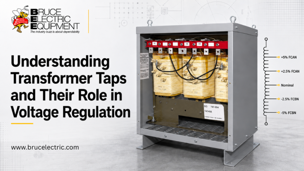
What Do Transformer Taps Do?
Transformer taps adjust the effective number of windings turns to compensate for a known primary-voltage deviation and keep secondary voltage closer to its rated value.
For example, a transformer rated 480V primary to 208Y/120V secondary may include taps for 504V, 492V, 480V, 468V, and 456V. If the actual incoming supply is 504V rather than 480V, selecting the 504V or +5% FCAN tap helps maintain the intended 208Y/120V secondary output.
Important: Standard dry-type transformer taps are fixed, de-energized settings. They are not automatic voltage regulators and do not continually adjust for changing voltage conditions.
Key Takeaways
• Transformer taps change the voltage ratio, not the transformer’s kVA capacity.
• FCAN taps are used when incoming primary voltage is above nominal.
• FCBN taps are used when incoming primary voltage is below nominal.
• Most commercial dry-type transformers use de-energized tap changing, meaning the transformer must be shut down before tap links or jumpers are moved.
• Taps can compensate for stable primary-voltage deviations but cannot fix overloads, undersized conductors, loose terminations, harmonic problems, or excessive feeder voltage drop.
• Always follow the transformer nameplate and manufacturer connection diagram; tap arrangements vary by model.
How Transformer Taps Adjust Secondary Voltage
A transformer operates according to its winding ratio:
Primary Voltage ÷ Secondary Voltage = Primary Turns ÷ Secondary Turns
In many dry-type transformers, taps are located on the primary winding. Selecting a different connection changes the effective number of primary winding turns and, therefore, the transformer’s voltage ratio.
When incoming primary voltage is higher than nominal, secondary voltage also rises unless the transformer is connected to the appropriate above-normal tap. When primary voltage is lower than nominal, a below-normal tap may be used to bring secondary voltage back toward its rated value.
Tap settings are designed to correct a known and relatively stable voltage condition. They are not a replacement for proper conductor sizing, voltage-regulation equipment, load analysis, or electrical-system troubleshooting.
FCAN vs. FCBN: What Do the Nameplate Markings Mean?
FCAN and FCBN are common nameplate designations used on transformer voltage-correction taps.
| Tap marking | Meaning | Use when measured primary voltage is | Typical effect |
|---|---|---|---|
| FCAN | Full Capacity Above Normal | Above rated primary voltage | Helps bring secondary voltage down toward nominal |
| Nominal | Rated primary connection | Near rated primary voltage | No correction required |
| FCBN | Full Capacity Below Normal | Below rated primary voltage | Helps bring secondary voltage up toward nominal |
The term “full capacity” means the transformer can operate at its rated kVA when connected according to the manufacturer’s nameplate instructions.
Easy Rule for FCAN and FCBN
• FCAN = Above Normal: Select it when incoming primary voltage is higher than the nameplate primary rating.
• FCBN = Below Normal: Select it when incoming primary voltage is lower than the nameplate primary rating.
A +5% FCAN tap does not add 5% to the secondary voltage. It is used when primary supply is approximately 5% above nominal.
Typical 480V Transformer Tap Settings
The following is a common example for a 480V primary transformer. Actual tap schedules vary by manufacturer, model, and voltage class.
| Tap connection | Primary voltage condition | Typical purpose |
|---|---|---|
| +5% FCAN | 504V | Corrects a primary supply approximately 5% above 480V |
| +2.5% FCAN | 492V | Corrects a moderately high primary supply |
| Nominal | 480V | Used when incoming voltage is near rated value |
| -2.5% FCBN | 468V | Corrects a moderately low primary supply |
| -5% FCBN | 456V | Corrects a primary supply approximately 5% below 480V |
Many transformers provide 2.5% and 5% above-normal and below-normal positions. Some models have wider, narrower, or asymmetric tap ranges. Never assume another transformer’s tap configuration applies to the unit in front of you.
Worked Example: 480V to 208Y/120V Transformer
Consider a three-phase transformer rated:
• Primary: 480V
• Secondary: 208Y/120V
• Measured primary voltage: 504V
If the transformer remains connected on the nominal 480V tap, the secondary voltage will rise by approximately 5%:
• 208V × 1.05 = approximately 218.4V line-to-line
• 120V × 1.05 = approximately 126V line-to-neutral
If the transformer nameplate includes a 504V or +5% FCAN connection, selecting that tap adjusts the voltage ratio for the measured 504V primary supply and helps restore the secondary output toward 208Y/120V.
The same principle applies in the other direction. If the measured primary voltage is approximately 456V, a -5% FCBN or 456V tap may be appropriate, depending on the manufacturer’s nameplate diagram.
De-Energized Tap Changers vs. On-Load Tap Changers
Most commercial and industrial dry-type transformers use a de-energized tap changer, also called an off-circuit or no-load tap changer.
| Feature | De-Energized Tap Changer (DETC) | On-Load Tap Changer (OLTC) |
|---|---|---|
| Adjustment method | Transformer must be de-energized | Designed to change taps while energized and carrying load |
| Typical use | Commercial and industrial dry-type transformers | Larger utility and substation transformers |
| Complexity | Manual links, jumpers, or tap leads | Advanced switching and control equipment |
| Voltage response | Fixed for a stable voltage condition | Can support voltage regulation during system operation |
For a standard dry-type transformer, tap links or leads must only be moved after the transformer has been isolated, de-energized, and made safe in accordance with the facility’s lockout/tagout procedures and applicable electrical-safety requirements.
On three-phase transformers, all coil sections must be set to the same manufacturer-specified tap position before the transformer is energized.
Multi-Tap Transformers, Center-Tapped Transformers, and Winding Taps
These terms are related but not interchangeable.
| Term | What it means | Main purpose |
|---|---|---|
| Transformer tap | A connection point on a winding | Fine voltage-ratio adjustment |
| Tap changer | The mechanism, link, or jumper used to select a tap | Moves the transformer to an available tap position |
| Multi-tap transformer | A transformer with multiple voltage connection options | Supports different nominal primary or secondary voltages |
| Center-tapped transformer | A secondary winding with a midpoint connection | Provides split-phase output, such as 120/240V |
| Feeder tap conductor | An NEC-related conductor term | Not related to transformer winding taps |
Important distinction: Transformer winding taps are not the same as feeder taps or tap conductors referenced in electrical-code discussions. This article addresses transformer winding taps used for voltage-ratio adjustment.
What Transformer Taps Can and Cannot Fix
Transformer taps can help when:
1. Primary voltage at the transformer terminals is consistently above or below nameplate voltage.
2. Secondary voltage is consistently high or low under normal operating conditions.
3. The transformer is correctly sized for the load.
4. A replacement transformer needs to match an existing site voltage condition.
5. The required adjustment is within the nameplate tap range.
Transformer taps cannot fix:
1. Transformer overload or inadequate kVA capacity.
2. Undersized conductors, excessive feeder length, or poor electrical connections.
3. Dynamic voltage dips during motor starts or switching events.
4. Harmonics, phase imbalance, grounding faults, or failed equipment.
5. A voltage mismatch beyond the transformer’s available tap range.
6. Incorrect voltage ratio between transformers operating in parallel.
If voltage problems occur only under load, review the transformer’s impedance, conductor sizing, load profile, power factor, motor-starting demand, and electrical connections. A tap setting cannot compensate for a system-design issue.
How to Select the Correct Transformer Tap Setting
Use this decision process before commissioning a new or replacement transformer:
1. Read the nameplate. Confirm the rated primary voltage, secondary voltage, phase, frequency, kVA, and available tap positions.
2. Measure incoming primary voltage. Take measurements at the transformer primary terminals under representative operating conditions.
3. Compare measured voltage with nameplate voltage. Determine whether incoming voltage is above, below, or near the rated primary value.
4. Use the manufacturer’s tap diagram. Choose the tap position that most closely matches the actual measured supply voltage.
5. De-energize before changing taps. Only qualified personnel should perform the work.
6. Verify secondary voltage after energization. Confirm that the secondary output is appropriate for the connected equipment.
7. Document the final setting. Record the measured voltage, selected tap, date, and technician information for maintenance and replacement records.
Parallel Transformer Warning
Do not change the tap setting of one transformer in a parallel bank without reviewing the complete paralleling arrangement. Parallel transformers require compatible voltage ratios, phase relationships, impedance characteristics, and connection configurations. A mismatch can create circulating current, uneven load sharing, overheating, or equipment damage.
Where Correct Tap Selection Matters Most
Tap configuration is especially important for replacement transformers serving control panels, VFDs, packaging equipment, imported European machinery, HVAC equipment, automation systems, data infrastructure, and industrial distribution equipment. In these applications, a transformer may have the correct kVA rating but still be unsuitable if its primary voltage, secondary voltage, phase, frequency, enclosure, or available tap range does not match the site conditions.
Need a Replacement Transformer With the Right Tap Range?
Before requesting a replacement transformer, gather:
• Transformer nameplate photo
• kVA rating
• Primary and secondary voltage
• Single-phase or three-phase configuration
• Frequency
• Measured primary voltage at the transformer terminals
• Current tap position, if known
• Enclosure or NEMA requirement
• Indoor, outdoor, industrial, OEM, medical, HVAC, VFD, or other application details
Bruce Electric has supplied electrical distribution equipment since 1973 and offers new, used, and reconditioned dry-type transformers for commercial and industrial applications. You can also review the broader transformer inventory, explore used and reconditioned electrical equipment, or use the transformer kVA calculator when reviewing transformer capacity requirements.
For assistance matching voltage, phase, kVA, enclosure, and tap configuration, request a transformer quote and include a clear nameplate photo with your application details.
Frequently Asked Questions
Q1. What is the difference between transformer taps and a tap changer?
Transformer taps are connection points on a winding. A tap changer is the mechanism, jumper, link, or switch used to select one of those connection points.
Q2. Do transformer taps increase kVA capacity?
No. Transformer taps change the voltage ratio; they do not increase the transformer’s kVA rating, current capability, or overload capacity.
Q3. Which tap should I use if my 480V supply measures 504V?
On a transformer nameplate that includes a +5% FCAN or 504V tap, that is typically the correct connection for approximately 504V incoming primary voltage. Confirm the exact arrangement using the manufacturer’s nameplate and wiring diagram.
Q4. Can I change transformer taps while the transformer is energized?
Most dry-type transformers use de-energized tap settings and must be shut down before adjustment. On-load tap changing is typically associated with larger utility or substation transformers, not standard dry-type units.
Q5. Can taps solve low voltage caused by long cable runs?
No. Taps may compensate for a stable primary-voltage deviation at the transformer terminals, but they do not correct conductor losses, undersized feeders, poor connections, transformer overload, or voltage sag caused by load and impedance.